


Description
4 Channel 5V Relay Module with Optocoupler
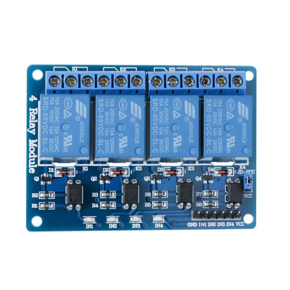
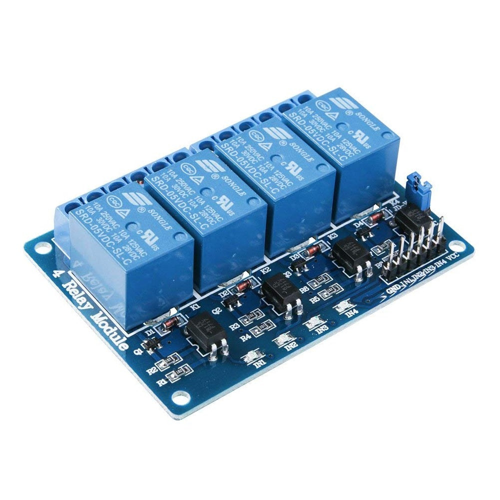
A 4x5V Opto-Isolated Relay Module is a board that contains 4 relays, each of which can be controlled by a microcontroller (like Arduino, ESP32, etc.) to switch AC or DC loads. Opto-isolation ensures that your control circuit is electrically isolated from the high-voltage side, enhancing safety.
Technical Specifications:
-
Operating Voltage: 5V DC
-
Relay Channels: 4
-
Trigger Signal Voltage: 0V (LOW) = ON, 5V (HIGH) = OFF (for LOW-level trigger boards)
-
Relay Type: SPDT (Single Pole Double Throw)
-
Indicator LEDs: Yes (One per relay, lights up when relay is ON)
-
Relay Contact Ratings: - 10A @ 250V AC & 10A @ 30V DC
-
Control Interface Pins: IN1, IN2, IN3, IN4, GND, VCC (+ JD-VCC on some boards)
-
Input Logic: TTL compatible (3.3V or 5V logic signals accepted, depending on the board)
- Mounting Holes: Usually 4 holes, one in each corner
Pinouts:

Connection with Arduino:
|
Relay Module Pin |
Arduino Uno Pin |
Description |
|
IN1 |
D7 |
Controls Relay 1 |
|
IN2 |
D6 |
Controls Relay 2 |
|
IN3 |
D5 |
Controls Relay 3 |
|
IN4 |
D4 |
Controls Relay 4 |
|
VCC |
5V |
Logic Power For Arduino |
|
GND |
Gnd |
Common ground |
|
JD-VCC |
5V (connected via jumper to VCC) |
Relay Coil Power |
Relay Output Terminal Layout (Per Relay)
|
Terminal |
Full Name |
Function |
|
NO |
Normally Open |
Disconnected when the relay is OFF. Connected to COM when the relay is ON. (Used to turn something ON when the relay is triggered) |
|
COM |
Common |
Common terminal between NO and NC. This is the central connection point. |
|
NC |
Normally Close |
Connected to COM when the relay is OFF. Disconnected when the relay is ON. (Used to turn something OFF when the relay is triggered) |

Sample code:
// Define relay control pins
int relay1 = 7;
int relay2 = 6;
int relay3 = 5;
int relay4 = 4;
void setup() {
// Set all relay pins as output
pinMode(relay1, OUTPUT);
pinMode(relay2, OUTPUT);
pinMode(relay3, OUTPUT);
pinMode(relay4, OUTPUT);
// Initialize all relays to OFF (HIGH for LOW-trigger modules)
digitalWrite(relay1, HIGH);
digitalWrite(relay2, HIGH);
digitalWrite(relay3, HIGH);
digitalWrite(relay4, HIGH);
}
void loop() {
// Turn ON relay 1
digitalWrite(relay1, LOW);
delay(1000);
digitalWrite(relay1, HIGH);
// Turn ON relay 2
digitalWrite(relay2, LOW);
delay(1000);
digitalWrite(relay2, HIGH);
// Turn ON relay 3
digitalWrite(relay3, LOW);
delay(1000);
digitalWrite(relay3, HIGH);
// Turn ON relay 4
digitalWrite(relay4, LOW);
delay(1000);
digitalWrite(relay4, HIGH);
delay(2000); // Wait before repeating the cycle
}